Wave Trap & Coupling Capacitor
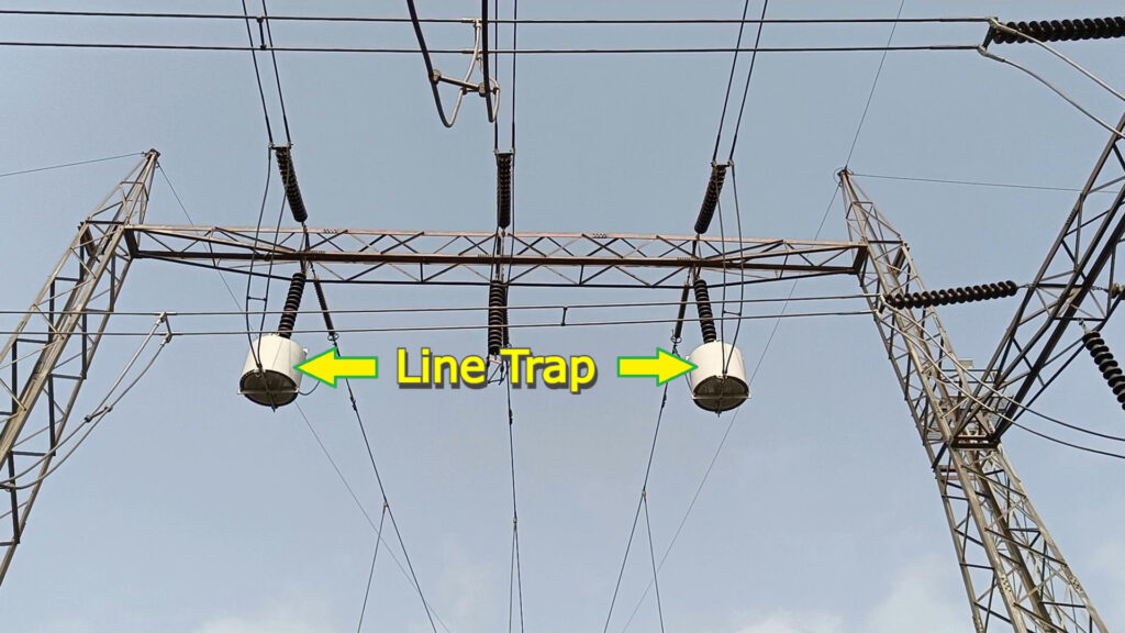
Let’s see the function of the Line Trap & coupling capacitor in PLCC, that is power line carrier communication. Usually, we see these hanging coils in an electrical substation. These coils are called Line Traps or Wave traps.
We know that, power transmission lines are used to transmit electric power. Using the same transmission lines, the carrier signal which is a high frequency signal is also transmitted.
This carrier signal is used for Telecommunication among electrical substations, Telemonitoring, and Teleoperation. Also, most importantly the carrier signals are used to protect the power transmission line against faults. Now as we know, the power frequency is 50 Hz or 60 Hz. And The carrier signal frequency is in kHz, which ranges from 3 kHz to 500 kHz depending upon the location. The carrier frequency range is different for different countries. In short, carrier signal frequency is significantly high as compared to the power frequency.

The difference in frequency is used to distinguish and separate the power signals and carrier signals. And this is done with the help of the Line Trap and coupling capacitor.
How? Let’s see.
Line Traps are connected in series with the power transmission line. And coupling capacitor is the connecting link between the power transmission line and the terminal assembly of the carrier signal panel, which is connected to the power transmission line before the Line Trap. Line Trap is nothing but an inductive coil with inductive reactance. And inductive reactance XL=2πfL. Here F is the frequency and L is the inductance of the coil. Hence Inductive reactance XL is proportional to the frequency. And as the name says this coupling capacitor is nothing but the capacitive reactance, and this capacitive reactance XC=1/2πfC. Here C is the capacitance. From this, we understand that XL is proportional to the frequency and XC is inversely proportional to the frequency. Hence Line Trap with inductive reactance XL offers high impedance for the high-frequency signals and low impedence to the low-frequency signals. Coupling capacitor with capacitive reactance offers low impedance to the high-frequency signals, and high impedance to the low-frequency signals. Hence high-frequency carrier signals get blocked by Line Trap, and travel through a coupling capacitor. And low-frequency power signals pass through Line Trap and get blocked by the coupling capacitor. This is how the high-frequency carrier signals and low-frequency power signals are separated and routed through the desired paths.
Now, let’s see, why do we need to separate these high-frequency carrier signals and low-frequency power signals. And route through different paths. If high-frequency carrier signals enter the power circuit of an electrical substation, it can damage electrical equipment. and similarly, the carrier signals panel can not withstand the power signals. This situation can lead to complete havoc in electrical substations, & subsequently in the power system.
Generally, we see only two Line Traps hanging. Power lines have three phases. Then, why only two Line Traps? The number of Line Traps depends upon the number of communication channels required for effective carrier signals communication.

Now let’s see the structure, components, and functions of Line Traps, and coupling capacitors. Let’s start with the Line Trap.
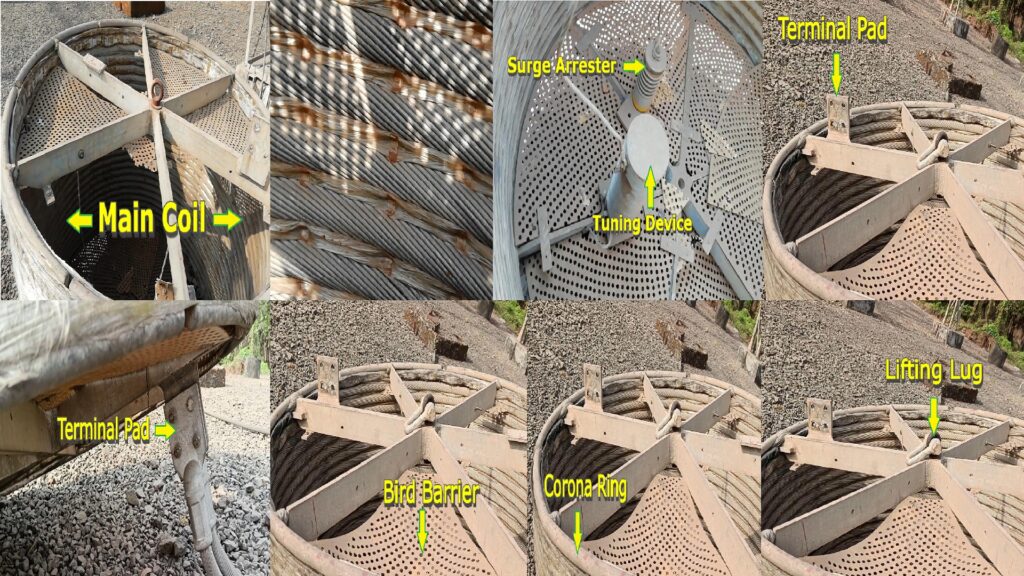
If we look closely, we can see that the design and the structure of the Line Trap are quite simple. The components of the Line Traps are the main coil, tuning device and protective device also called a surge arrester. The main coil is made from a stranded aluminum conductor. The current carrying capacity of the Line Trap is decided based on the number of strands in the coil. That means the more the number of strands, the more is the cross-section area of the coil. And more the cross-section area, the more is the current carrying capacity of the coil. This stranded aluminum coil is wound in a single layer or multiple layers. For heat dissipation, a separation between layers is required. So, the cooling ducts are created in between the two layers of the coil, with spacer bars made out of epoxy resin and fiberglass.
The next important component is the tuning device. It is installed inside and in parallel with the main coil. The tuning device consists of coils, capacitors, and resistors, all packed in a weatherproof enclosure filled with resin, and foam for protection from weather conditions. And it adjusts blocking frequency or bandwidth. There are three types of tuning devices, wideband tuning, single-frequency tuning, and double frequency tuning.
Another main component of the line trap is the protective device also called a surge arrester which is connected in parallel with the main coil and the tuning device. This surge arrester protects the main coil and the tuning device from surge voltages, and also from over-voltage levels.
Some more components of the Line trap are, terminal pads for connections, a bird barrier, a corona ring, and a lifting lug.
Now, let’s see another main component, the coupling capacitor. It is mounted either separately or below the line trap. Its function is to block low-frequency power signals and allow high-frequency carrier signals.
