Basics of Magnetism – All the related topics at one place

What is Magnet?

What is Magnet: A magnet is a an object or material that produces a magnetic field.

Natural Magnet: Magnetite

Artificial Magnet: Electromagnet, Alnico, aluminium (Al), nickel (Ni), and cobalt (Co), hence the acronym al-ni-co.


Magnetic Field

The space around the magnetic poles is called as the magnetic field. It is represented by the magnetic lines of force.

Important Terms related to Magnetism

Magnetic Flux Φ : Magnetic flux is defined as the number of magnetic field lines passing through a given surface

SI Unit: Weber

CGS Unit: Maxwell.

Magnetic Flux Density B : The magnetic flux density is the number of lines of force passing through a unit area of material

B = Φ /A

Unit: Weber/Sq. meter Or T

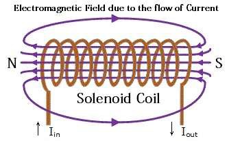
Magnetic Field Strength (Intensity) H due to solenoid with length l , turns N & I is given as

H = NI/l

Unit: AT/m. 

Relation Between Magnetic Flux Density B & Magnetic Field Intensity (Strength) H

B = μ H

Where

μ = Magnetic Permeability

B = μ0 μr H

Where

μ0 = Permeability of Free Space

μr = Relative Permeability (Material.

Reluctance & Permeance:

Reluctance S is given as: l/μa AT/ Wb

Where

μ = Magnetic Permeability

Permeance is given as:

Permeance = 1 /Reluctance Wb /AT or Henry

μr = Relative Permeability = 1 (for air)

Determination of Ampere Turn : In any magnetic circuit, flux created is given as

AT = MMF Unit: AT or Gilbert

MMF: Magneto Motive Force

Flux = MMF / Reluctance Wb.

Magnetic Moment : is defined as magnetic strength and orientation of a magnet or other object that produces a magnetic field.

The Magnetic moment for the current loop is the product of the current flowing and the area

M = IA

Unit: Amp-m ² or J/Tesla

Magnetic Dipole Moment M : is defined as two unlike poles of equivalent strength and separated by a small distance

M = m2l

Where

m = power of any magnetic pole

2l = distance between the two poles

Unit: wb *m.

Intensity of Magnetization J : It is the magnetic dipole moment acquired per unit volume

It shows the extent to which the substance is magnetized. Also it is defined as the pole strength per unit area

J = m/a

Unit: Amp/meter.


Electromagnetism

Magnetic Field due to Current Carrying Conductor : when a conductor carries an electric current, a magnetic field is produced all along its length.

• The magnetic lines of force form concentric circle around the conductor

• The direction of the current & the direction of magnetic field are at right angle to each other.

• The magnitude & direction of the magnetic field depends upon the current magnitude & direction respectively.

The direction of Magnetic Field due to Current Carrying Conductor

• The direction of lines of force (magnetic field) around a straight

current carrying conductor can be determined by any of the following rules

1. Ampere s Rule

2. Cork Screw Rule

3. Right Hand Rule.

1. Ampere s Rule:

Assume current flows from feet to head of observer s body, then on facing the compass needle the north pole will be deflected towards observer s left

2. Cork Screw Rule:

The right handed cork screw held with its axis parallel to the conductor pointing the direction of flow of current and the head of the screw is rotated in such a direction that the screw moves in the direction of flow of current then the direction in which the head of screw is rotated, will be the direction of magnetic field or lines of force.

3. Right Hand Rule:

If the current carrying conductor is held in right hand by the observer so that it is encircled by fingers stretching the thumb at right angle to the fingers in the direction of flow of current then finger tips will point the direction of magnetic lines of force

Solenoid

• The current carrying wire wound spirally in the form of helix about an axis is known as solenoid or coil.

• Magnetic field produced due to current carrying solenoid is fairly uniform in the middle of the coil over a small region.

• It acts just like a bar magnet with north and south pole.

Biot Savart law :

It states that for a closed current carrying loop, magnetic strength is equal to 1/4 π times the current and line integral of the cross product of radius vector with surface area element.

• An equation which describes the magnetic field generated by a constant electric current

H =1/ 4 π  (ds X R) / R ²

B = μH = μI/4π ∫(ds X R) / R ²

H=Magnetic Field Intensity (Strength)

B=Magnetic Field Intensity

μ=Magnetic Permeability

I=Current

R=Radius

Ampere s Circuital Law / Ampere s Work Law :

It states that the line integral of H around a single closed path is equal to the current

enclosed

H.dl = I

For N Turns

H.dl= NI

Hl= NI

Force on a Current Carrying Conductor Lying in the Magnetic Field:

When a current carrying conductor is placed at right angle to the direction of magnetic field, a mechanical force is experienced on the conductor in a direction perpendicular to both the direction of magnetic field and flow of current.

The Magnitude of the Force F in Newton is given by

F = BIl

Where B =Flux Density in Tesla

I =Current through conductor in Ampere

l=Length of the conductor in Meters

If the conductor is lying at an angle θ with a magnetic field or flux density B Tesla, then General Equation for the Mechanical force experienced on a current carrying conductor is given by

= BIlsin θ

Force on a Current Carrying Conductor Lying in the Magnetic Field:

The Direction of the force can be determined by applying Flemings Left Hand Rule

Field Strength due to a Solenoid:

A Solenoid having length l meters, turns N & Current I amperes has the Field Strength H

H = N I / l   AT/m

Force Between Two Parallel Current Carrying Conductor:

Magnitude of the Force Between Two Conductors is

F = (2xI1xI2xl×10 -7 )/d   N

Where

l = Length of each conductor in meters

I1 = Current in Conductor 1 in Amps

I2 = Current in Conductor 2 in Amps

d = Distance between two conductors in meter

Dynamically Induced EMF

When a conductor of length l meters is moved in a magnetic field of strength B Wb /m ² with a velocity v m/s in a direction perpendicular to its own length and at an angle θ to the direction of magnetic field, the induced emf will be given as

e = Bvlsinθ  volts

The direction of this induced emf is given by Fleming s right hand rule

Statically Induced EMF

Statically Induced EMF can be

1. Self induced EMF

2. Mutually induced EMF

1. Self induced EMF: 

When the current flowing through a coil is changed, the flux linking its own winding changes and due to the change in linking flux with the coil, an EMF known as self induced EMF is induced

• Lenz s Law: according to lenz s law, any induced emf opposes the cause. Hence in case of Self induced emf also, the induced emf opposes the cause, that is change of current.

• This happens due to the property of the coil, called as Self inductance

Consider a solenoid of length l meters, area of cross section a sq. meters, number of turns N and of relative permeability μ r . When the current flowing through solenoid is changed,

Self Induced EMF   e = -(N ² μ r μ 0 a/ l ) di/dt

The term (N ² μ r μ 0 a/ l ) is constant for any given coil or circuit called as coefficient of self inductance. It is represented by symbol L unit is Henry

Hence, Self Induced EMF 

e= L di/ dt

Where  L = N ² μr μ0 a/ l   Henry

Mutually Induced EMF :

The phenomenon of generation of induced emf in a coil by changing the current in the neighboring coil is called the mutual induction and emf so induced is called as the mutually induced EMF

• Consider a coil one with length l meters, cross section area a sq. meters, number turns N 1 and relative permeability μ r . Now consider another coil two with number of turns N 2 is placed near coil one. Now current flowing in coil one is changed.

Mutually induced EMF

= -(N1 N2 μr μ0 a/ l ) di/dt

Here flux leakage is neglected

The term (N 1 N 2 μ r μ 0 a/ l ) is called as coefficient of mutual induction of coil two with respect to coil one. It is represented by M and unit is Henry

Hence Mutually induced emf

em = M di/ dt

Where M = (N1 N2 μr μ0 a/ l)

Inductances in Series : Additive

When the coils are connected in series such as their fluxes ( mmf ) are additive i.e. in the same direction as in the fig. the equivalent inductance of the combination is given as

L = L1 + L 2 + 2 M

Where L1 , L 2 Coefficient of Self inductance of Coil 1 and 2 respectively,

M = Coefficient of Mutual inductance

Inductances in Series: Subtractive

When the coils are connected in series such as their fluxes ( mmf ) are Subtractive i.e . in opposite direction as in the fig. the equivalent inductance of the combination is given as

L = L1 + L 2 – 2 M

Where L1 , L 2 Coefficient of Self inductance of Coil 1 and 2 respectively,

M = Coefficient of Mutual inductance

Inductances in Parallel : Additive

When two coils of self Inductances L 1 & L 2 and Mutual inductance M are connected in parallel as shown in fig, the equivalent inductance of the combination is given as

L = (L1 L2  – M ² )/(L 1 + L 2 + 2 M)

When mutual flux helps the individual flux

Inductances in Parallel : Subtractive

When two coils of self Inductances L 1 & L 2 and Mutual inductance M are connected in parallel as shown in fig, the equivalent inductance of the combination is given as

L= (L1 L2 – M ² )/(L 1 + L 2 + 2 M)

When mutual flux opposes the individual flux

Leave a Comment

Your email address will not be published.