LA LCM - Lightning/Surge Arrester Leakage Current Measurement
LA LCM – Leakage current measurement of a Lightning Arrester also called a Surge Arrester. We will see, why do we need to measure the LA leakage current? And how do we measure the leakage current? With example.
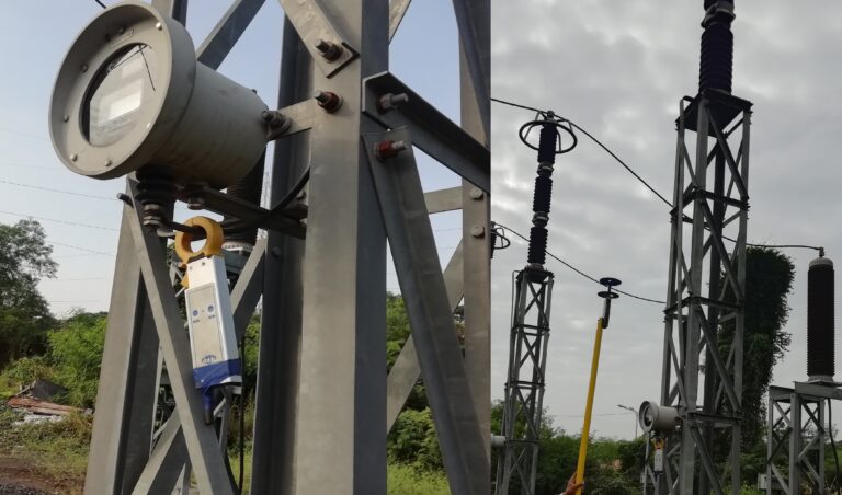
First, let’s see, why do we need to measure LA leakage current? We know that there is a leakage current meter installed on the support structure of LA.
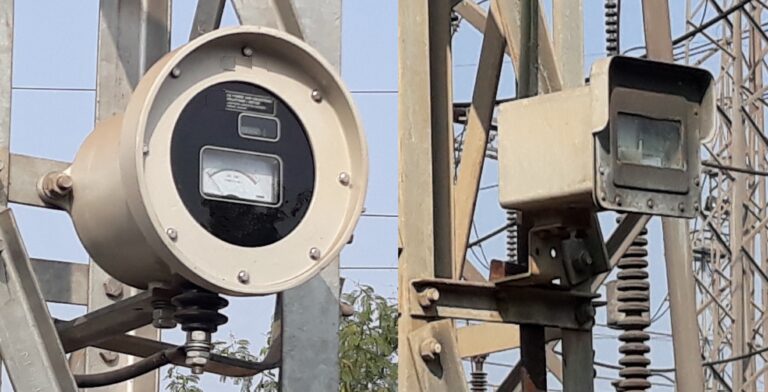
This meter continuously measures and displays the leakage current flowing through LA, and counts the number of surges experienced by LA. Then why do we need to measure leakage current separately? The meter installed, measures the total leakage current through LA. But this total leakage current is a vector sum of the capacitive and the resistive current through LA. And to know the healthiness of LA accurately, we need to check the resistive component (Ir) of the total leakage current (It).
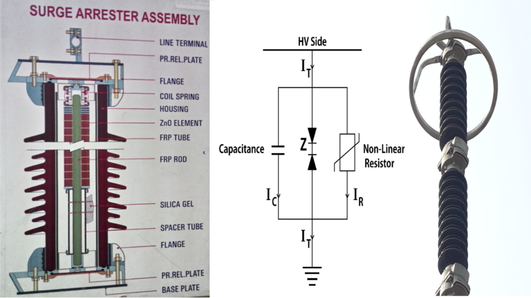
Because we know the main component of LA is zinc oxide element also called ZnO blocks. LA is nothing but a stack of ZnO elements.
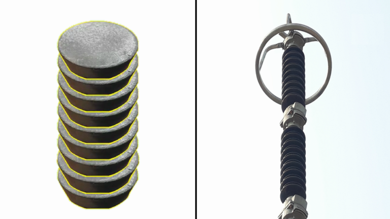
The size and number of ZnO elements for a particular LA are decided based on the rating and design of that LA. The healthiness of LA is nothing but the intactness of the insulation property of these ZnO blocks. Hence, to measure the insulation level of these ZnO blocks accurately, we need to measure resistive leakage current (Ir), through these blocks, and not the total leakage current (It).
Now to understand this further, we represent, LA with a circuit diagram also called an equivalent circuit diagram. The top-end, line terminal of the LA is connected to a High voltage line. And LA ground terminal is connected to the earth. We can see both Capacitive Current (Ic) and resistive current (Ir). Adding to total leakage current (It). As in the phasor diagram, resistive leakage current (Ir) is in phase with applied LA terminal voltage (V). Capacitive current (Ic) leads (Ir) by 90 degrees. Capacitive current (Ic) is large as compared to (Ir), & practically (Ic) remains constant. Whereas, resistive leakage current (Ir) increases over time, due to lightning impulse, fault, aging, moisture ingress, or insulation failure of Surge Arrester. Resultant leakage current (It) is the vector sum of (Ir) & (Ic). The magnitude of total leakage current (It) is equal to the square root of the addition of squares of (Ir) & (Ic).
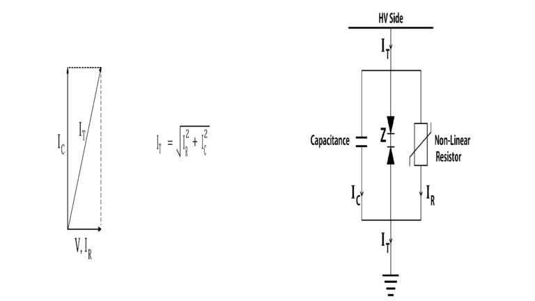
Now, let’s say, the resistive leakage current (Ir) of LA increases over time to a new value (Ir1). Hence, the new resultant leakage current (It) also increases and becomes (It1). Similarly, if resistive leakage current (Ir1) again increases to a new value (Ir2), due to some reasons, mentioned earlier. New, increased, total leakage current will be (It2).
If we plot these different values of (Ir) and (It), separately. We notice a very important point here. We can see, that even if there is a significant increase in resistive leakage current (Ir), the respective increase in the resultant leakage current (It) is very small. This happens because the value of (Ic) is very large as compared to the value of (Ir). Also, practically (Ic) remains constant. Hence, even large changes in (Ir) do not affect much the value of (It).

And this is the reason, we need to check the resistive leakage current value (Ir) separately, to know LA’s condition. Total leakage current (It) alone does not show the exact condition of LA. This installed leakage current meter shows only the total leakage current (It). And does not show resistive leakage current (Ir) separately. Even though resistive leakage current in LA increases significantly. The meter will show a very small increase in total leakage current. This may mislead, the assessment of LA healthiness.
Now, let’s see, how we measure resistive leakage current (Ir) and total leakage current (It), with an example. This is the LCM kit which is a leakage current measurement kit, with a CT unit, a field probe unit and FRP rod that is a fiber-reinforced-plastic rod. The kit, CT unit & probe unit, are charged fully, before use.

Moving on to the connection & function part. All the necessary connections of the LCM kit, CT unit & field probe unit are done. Kit earthing is done through this master earthing point. Safety and measurement point of view, kit earthing is the most important point. Hence proper earthing is very essential. We can see the RF antenna which is a radiofrequency antenna, installed at this point. We can see, that both CT & field probe units also have a similar antenna attached. These three antennas communicate with each other wirelessly.
The CT unit is clamped around the cable or the conductor, connected between the counter and LA bottom, just before the counter. The CT unit measures total leakage current along with total harmonics, that is system generated harmonics and harmonics due to ZnO blocks. The field probe unit is firstly fitted on the FRP rod, with these two discs installed, as in the picture. Then the field probe unit is held at the level of the LA base. Please do not touch this field probe unit to the base of LA, or any live part, under any circumstances. This will damage the unit.
This field probe unit measures system harmonics. Since it is not connected to the LA circuit at all. It only deals with system voltage and measures system harmonics. And these system harmonics are used as a reference and are deducted from the total harmonics measured by the CT unit. Leaving behind only those harmonics, which are generated by ZnO blocks that is LA. In some measurement kits, system harmonics compensation is not done using the field probe unit. And 3rd harmonic resistive leakage current is measured without system harmonic compensation. But for more accuracy, it is better to use system harmonic compensation.
The next obvious question is, why do we need to do system harmonic compensation for better accuracy? We know that non-linear loads and equipment, such as transformers, motors, wave-traps, etc. are connected in electrical substations. Harmonics are generated due to these non-linear loads, which include the third harmonic also. On the other hand, harmonics are also generated in the LA ZnO block, due to the non-linear resistive properties of ZnO elements. Which are mostly comprised of 3rd harmonics. Since 3rd harmonic component is predominant in the resistive leakage current of ZnO blocks, which is roughly around 10% to 40% of resistive leakage current. Hence, we focus, mainly on calculating the third harmonics due to ZnO blocks only, and not the system harmonics, for the exact health assessment of LA. Because this 3rd harmonic resistive leakage current is the main cause of deterioration of ZnO blocks. And subsequently LA failure. That’s why we do system harmonic compensation for better accuracy.
To brief it, simply. We can say, the CT unit measures total leakage current along with system-generated harmonics and harmonics generated due to ZnO blocks since it is clamped directly to the LA counter cable. Whereas the Field probe unit measures only system harmonics since it is not connected to the LA circuit. Hence CT unit measured values minus field probe unit measured values, gives ZnO generated harmonics values.
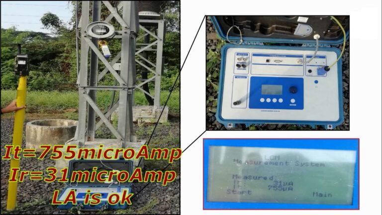
Now, once the connections and measurement set-up are ready, we press the test button on the kit. We get this reading. Total leakage current and resistive leakage current. Now, to decide, whether LA is healthy or not. We need to see the resistive leakage current value (Ir). This (Ir) value ranges from 10 microamperes to 600 microamperes, depending upon the rating, design, and age of LA. In this example, the total leakage current (It) is 755 microamperes. And resistive leakage current (Ir) is 31 microamperes. We can say, the condition of this LA is ok, based on the (Ir) value.
Now, let’s look at another example. Here, the total leakage current (It) is 715 microamperes. And resistive leakage current (Ir) is 306 microamperes. Now, this (Ir) value looks doubtful.
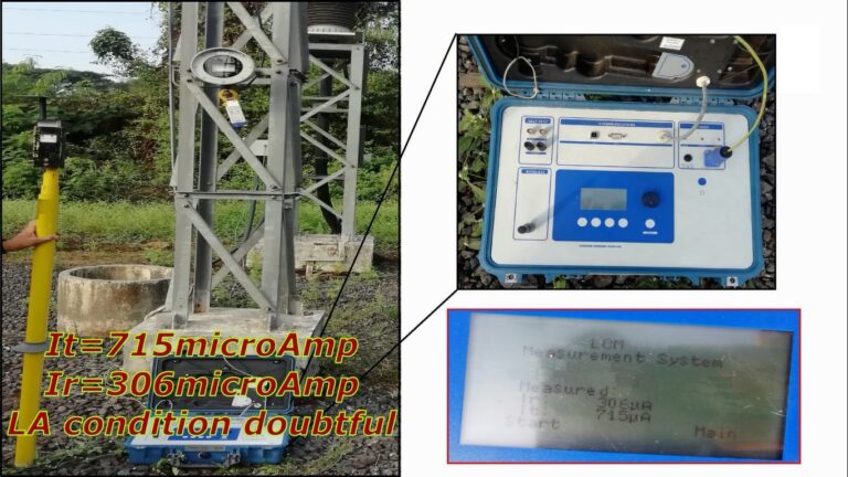
In this case, we should check previously measured (Ir) values of this LA. And compare it with this (Ir) value. If there is an increase in the resistive leakage current of the LA. Then LA must be taken out of the service immediately, after consulting with the LA manufacturer. It is important to keep a track of the (Ir) values of the LA. And observe the trend. If the (Ir) value is increasing over time, that means, LA is losing its insulation property. And it may fail anytime.
Also, environmental conditions affect (Ir) value. With high ambient temperature, the (Ir) value increases. Nowadays, modern measurement kits have the inbuilt ability to calculate and correct the (Ir) value to standard temperature, which is 20 degrees Celsius. Also, other environmental factors such as humidity, dust & rain affect the (Ir) value.